
搜索到
80
篇与
的结果
-
 快速部署kubernetes 关闭防火墙systemctl stop firewalld && systemctl disable firewalld关闭所有节点的 SELinux ,将 SELinux 设置为 permissive 模式(相当于将其禁用)sudo setenforce 0 sudo sed -i 's/^SELINUX=enforcing$/SELINUX=permissive/' /etc/selinux/config设置主机名hostnamectl set-hostname master关闭 Swapswapoff -a && sysctl -w vm.swappiness=0永久关闭swap (推荐)sed -i '/swap/s/^\(.*\)$/#\1/g' /etc/fstab主机添加 hosts:cat >> /etc/hosts << EOF 10.0.0.24 master 10.0.0.25 node1 10.0.0.26 node2 EOF配置路由转发IPv4 并让 iptables 看到桥接流量cat <<EOF | sudo tee /etc/sysctl.d/k8s.conf net.bridge.bridge-nf-call-iptables = 1 net.bridge.bridge-nf-call-ip6tables = 1 net.ipv4.ip_forward = 1 EOF应用 sysctl 参数而不重新启动sudo sysctl --system使用部署工具来安装 Kubernetesk8s社区提供了3个部署工具,分别是kubeadm, kops和 Kubespray ,这里有详细的说明配置Kubernetes的阿里云yum源Debian / Ubuntuapt-get update && apt-get install -y apt-transport-https curl https://mirrors.aliyun.com/kubernetes/apt/doc/apt-key.gpg | apt-key add - cat <<EOF >/etc/apt/sources.list.d/kubernetes.list deb https://mirrors.aliyun.com/kubernetes/apt/ kubernetes-xenial main EOF apt-get update apt-get install -y kubelet kubeadm kubectlCentOS / RHEL / Fedoracat <<EOF > /etc/yum.repos.d/kubernetes.repo [kubernetes] name=Kubernetes baseurl=https://mirrors.aliyun.com/kubernetes/yum/repos/kubernetes-el7-x86_64/ enabled=1 gpgcheck=1 repo_gpgcheck=1 gpgkey=https://mirrors.aliyun.com/kubernetes/yum/doc/yum-key.gpg https://mirrors.aliyun.com/kubernetes/yum/doc/rpm-package-key.gpg EOF setenforce 0这里指定版本#yum install -y kubelet kubeadm kubectl yum install -y kubelet-1.23.4 kubeadm-1.23.4 kubectl-1.23.4 systemctl enable kubelet && systemctl start kubelet * 由于官网未开放同步方式, 可能会有索引gpg检查失败的情况, 这时请用以下命令安装:yum install -y --nogpgcheck kubelet-1.23.4 kubeadm-1.23.4 kubectl-1.23.4k8s-master初始化主节点kubeadm init \ --apiserver-advertise-address=10.0.0.24 \ --image-repository registry.aliyuncs.com/google_containers \ --kubernetes-version v1.23.4 \ --service-cidr=10.96.0.0/12 \ --pod-network-cidr=10.244.0.0/16注(所有节点):vi /etc/docker/daemon.json"exec-opts": [ "native.cgroupdriver=systemd" ],重启dockersystemctl restart docker重置 kubeadm 安装的状态kubeadm reset在初始化 (9)在主节点上设置 Kubernetes 配置在主节点上配置kubectl工具并设置集群证书mkdir -p $HOME/.kube sudo cp -i /etc/kubernetes/admin.conf $HOME/.kube/config sudo chown $(id -u):$(id -g) $HOME/.kube/config或者,如果你是 root 用户,则可以运行:export KUBECONFIG=/etc/kubernetes/admin.conf安装pod网络插件在两个工作节点上加入 Kubernetes 集群sudo kubeadm join 主节点IP:主节点端口 --token <hz1ri9.qca0lj1qii44l58c> --discovery-token-ca-cert-hash sha256:<hash>例如:sudo kubeadm join 10.0.0.24:6443 --token 37mtsv.c32oz3fgbkckoh11 --discovery-token-ca-cert-hash sha256:8da41125c132639053ca58018e57477453b51f8e344ec0a1d8709c8e432a4ada等待一段时间,直到 Kubernetes 集群所有的节点都处于 Ready 状态。可以使用以下命令查看节点的状态:sudo kubectl get nodes
 -
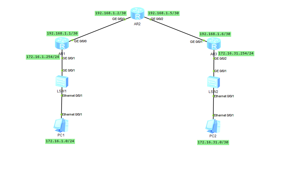
RIPv2 基础配置 配置思路:我们将在每台路由器上部署RIPv2,使得网络中各个网段之间能够实现相互通信。此外,R1及R2和R3运行RIPv2,为了使得R1和R3能够通过RIP学习到去往 PC端 的路由,我们需要在R1和 R3 的接口上激活RIPv2, 但是接口一旦激活RIPv2,R1/3 便会周期性地从该接口发送 Response报文,然而其直连的网段中并不存在其他的RIP路由器,因此这些RIP报文实际上造成了该网段内PC的额外负担。解决这个问题的办法非常简单,就是将R1/3 的接口配置为 Silent-Interface。R1:rip命令用于创建一个RIP路由进程,而该命令后的数字1则为该RIP进程的进程 ID (Process-ID),Process-ID 如果不手工指定,则系统会自动为该进程分配一个。rip 1在RIP配置下执行的version 2命令用于指定该进程所运行的RIP版本为RIPv2。version 2Network命令用于在指定网段的接口上激活RIP。值得注意的是,network命令所指定的必须是主类网络地址,而不能是子网地址。例如network 192.168.1.0这条命令,将使得R1在GEO/O/1接口上激活RIPv2,而 network 172.16.0.0命令则使得R1在GEO/0/2接口上激活RIPv2。network 192.168.1.0 network 172.16.0.0silent-interface GigabitEthernet 0/0/1 命令用于将GEO/O/1接口配置为Silent-Interface。如此一来,R1将不会再从该接口发送Response报文。silent-interface GigabitEthernet 0/0/1R2:rip 1 version 2 network 192.168.1.0R3:rip 1 version 2 network 192.168.1.0 network 172.16.0.0在完成上述配置后,我们可以通过以下命令来对配置进行验证。display rip 1 database 查看RIP进程1的数据库display rip 1 interface 查看本设备有哪些接口激活了RIP
-
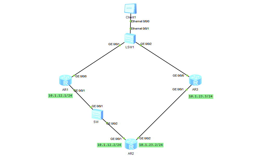
静态路由与NQA联动 1. 配置思路:续上 静态路由与BFD联动 依然是相同的需求,此时只需要在R2上部署一个NQA的实例,使用ICMP测试机制探测到Rl (10.1.12.1)的可达性,并将测试结果与下一跳为R1的静态路由进行联动即可。当NQA检测到10.1.12.1可达时,静态路由生效,当检测到其不可达时,静态路由失效,此时浮动路由将出现在路由表中。R2:admin 是测试实例的管理者名称, smiling 是测试实例名,这两个名称都是自定义的。nqa test-instance admin smilingTest-type 命令定义了该测试实例使用的测试机制为ICMP :test-type icmpdestination-address 定义的是测试对象的ip 地址:destination-address ipv4 10.1.12.1frequency 定义的是每一轮测试的时间间隔(单位为秒):frequency 6probe-count 命令定义了每一轮测试的探测次数:probe-count 2interval seconds 定义了在每一轮测试当中每个探测报文的发送间隔(单位为秒):interval seconds 2timeout 定义了每一次探测的超时时间(单位为秒), shart now 命令使该测试实例开始执行。timeout 2 shart now接下来为 R2 配置静态路由,将静态路由 ip route-static 10.9.9.0 255.255.255.010.1.12.1与 admin testl这个NQA实例进行联动,然后再另外配置一条浮动静态路由:ip route-static 10.9.9.0 255.255.255.0 10.1.12.1 track nqa admin smiling ip route0static 10.9.9.0 255.255.255.0 10.1.23.3 preference
-
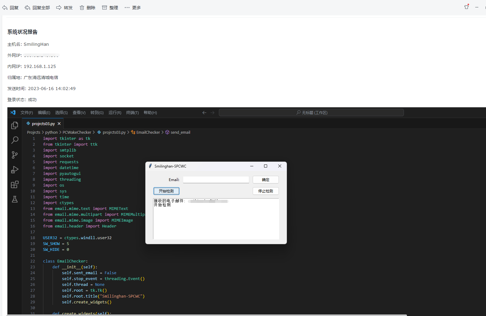
TanHaX-SPCWC 刚考完试闲得发慌写的。Smilinghan-SPCWC 是一个 Python 程序,允许用户监控计算机的系统状态并发送电子邮件通知。该程序使用 tkinter 库创建图形用户界面 (GUI),使用 smtplib 库发送电子邮件。还使用了其他库,如 socket、requests、datetime、pyautogui、threading、os、sys、time 和 ctypes。import tkinter as tk from tkinter import ttk import smtplib import socket import requests import datetime import pyautogui import threading import os import sys import time import ctypes from email.mime.text import MIMEText from email.mime.multipart import MIMEMultipart from email.mime.image import MIMEImage from email.header import Header USER32 = ctypes.windll.user32 SW_SHOW = 5 SW_HIDE = 0 class EmailChecker: def __init__(self): self.sent_email = False self.stop_event = threading.Event() self.thread = None self.root = tk.Tk() self.root.title("TanHaX-SPCWC") self.create_widgets() def create_widgets(self): mainframe = ttk.Frame(self.root, padding="20 10 20 10") mainframe.grid(column=0, row=0, sticky=(tk.N, tk.W, tk.E, tk.S)) mainframe.columnconfigure(0, weight=1) mainframe.rowconfigure(0, weight=1) email_entry = ttk.Entry(mainframe, width=30) email_entry.grid(column=1, row=0, sticky=(tk.W, tk.E)) email_label = ttk.Label(mainframe, text="Email:") email_label.grid(column=0, row=0, sticky=tk.E) submit_button = ttk.Button(mainframe, text="确定", command=lambda: self.submit_email(email_entry)) submit_button.grid(column=2, row=0, sticky=tk.W) start_button = ttk.Button(mainframe, text="开始检测", command=self.start_thread) start_button.grid(column=0, row=2, sticky=tk.W) stop_button = ttk.Button(mainframe, text="停止检测", command=self.stop_thread) stop_button.grid(column=2, row=2, sticky=tk.E) output_text = tk.Text(mainframe, height=10, width=50) output_text.grid(column=0, row=3, columnspan=3, sticky=(tk.W, tk.E)) for child in mainframe.winfo_children(): child.grid_configure(padx=5, pady=5) email_entry.focus() self.root.bind('<Return>', lambda event: self.submit_email(email_entry)) self.output_text = output_text def submit_email(self, email_entry): email = email_entry.get() self.output_text.insert(tk.END, "接收的电子邮件: " + email + "\n") with open("emails.txt", "w") as f: f.write(email + "\n") email_entry.delete(0, tk.END) email_entry.insert(0, "") def send_email(self, subject, content, receiver): sender = 'smilinghan@qq.com' password = 'password' with open("emails.txt", "r") as f: receivers = [f.read().strip()] message = MIMEMultipart() message['Subject'] = Header(subject, 'utf-8') message['From'] = Header(sender) message['To'] = Header(receiver) text = MIMEText(content, 'html', 'utf-8') message.attach(text) screenshot = pyautogui.screenshot() if screenshot is not None: screenshot.save('screenshot.png') with open('screenshot.png', 'rb') as f: img = MIMEImage(f.read()) img.add_header('Content-ID', '<screenshot>') message.attach(img) try: smtpObj = smtplib.SMTP_SSL('smtp.qq.com', 465) smtpObj.login(sender, password) smtpObj.sendmail(sender, receivers, message.as_string()) self.output_text.insert(tk.END, "邮件发送成功\n") self.sent_email = True except Exception as e: self.output_text.insert(tk.END, "邮件发送失败\n") self.output_text.insert(tk.END, str(e) + "\n") self.sent_email = False def check_system(self, receiver): try: while not self.stop_event.is_set(): if USER32.GetForegroundWindow() != 0: hostname = socket.gethostname() ip_address = socket.gethostbyname(hostname) response_ip = requests.get("https://www.90th.cn/api/ip") if response_ip.status_code == 200: public_ip = response_ip.json()["ip"] address = response_ip.json()["address"] else: public_ip = "获取失败" address = "获取失败" login_time = datetime.datetime.now().strftime("%Y-%m-%d %H:%M:%S") subject = '系统状况报告' content = f""" <html> <body> <h3>系统状况报告</h3> <p>主机名: {hostname}</p> <p>外网IP: {public_ip}</p> <p>内网IP: {ip_address}</p> <p>归属地: {address}</p> <p>发送时间: {login_time}</p> <p>登录状态: 成功</p> <p><img src="cid:screenshot"></p> </body> </html> """ if not self.sent_email: self.send_email(subject, content, receiver) self.sent_email = True time.sleep(5) else: time.sleep(1) self.sent_email = False self.output_text.insert(tk.END, "电脑未唤醒\n") except Exception as e: self.output_text.insert(tk.END, "Error: 无法检测电脑唤醒状态\n") self.output_text.insert(tk.END, str(e) + "\n") self.sent_email = False def start_thread(self): if self.thread is None or not self.thread.is_alive(): with open("emails.txt", "r") as f: receiver = f.read().strip() self.thread = threading.Thread(target=self.check_system, args=(receiver,), daemon=True) self.thread.start() self.output_text.insert(tk.END, "开始检测\n") def stop_thread(self): if self.thread is not None and self.thread.is_alive(): self.stop_event.set() self.thread.join(timeout=3) self.output_text.insert(tk.END, "停止检测\n") def run(self): if getattr(sys, 'frozen', False): os.chdir(sys._MEIPASS) self.root.protocol("WM_DELETE_WINDOW", self.stop_check) self.root.mainloop() def stop_check(self): if not self.stop_event.is_set(): self.stop_event.set() if self.thread is not None and self.thread.is_alive(): self.thread.join(timeout=3) self.stop_thread() self.root.destroy() self.root.quit() for t in threading.enumerate(): if t != threading.current_thread(): t.join(timeout=3) if __name__ == '__main__': checker = EmailChecker() checker.run(){lamp/}安装克隆存储库或下载文件。确保计算机上已安装 Python。运行以下命令安装所需的库:pip install -r requirements.txt使用打开命令提示符或终端,导航到文件所在的目录。运行以下命令启动程序:python email_checker.py程序将打开一个 GUI 窗口。在“电子邮件”字段中输入您的电子邮件地址,然后单击“确定”按钮。单击“开始检测”按钮以开始监控系统状态。如果计算机处于唤醒状态并正在使用,程序将每 5 秒发送一封包含系统信息和屏幕截图的电子邮件。如果计算机处于空闲或睡眠状态,程序将不会发送任何电子邮件。要停止监控,请单击“停止检测”按钮。注意事项该程序使用 邮件服务器发送电子邮件。请确保您拥有一个邮箱账户或者邮箱服务器,并在 send_email 方法中提供正确的电子邮件地址和密码。该程序将电子邮件地址保存在名为 "emails.txt" 的文件中。请确保该文件与程序位于同一目录中。该程序使用 pyautogui 库进行屏幕截图。请确保您已安装该库并具有进行屏幕截图的必要权限。该程序使用线程在后台运行监控过程。stop_event 用于在用户单击“停止检测”按钮时停止监控过程。程序将在 GUI 窗口中显示输出消息。
-
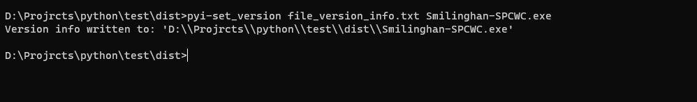
使用 pyi-set_version 为 Python EXE 文件添加版本信息的方法 在开发软件时,为了方便用户了解软件的版本信息,我们通常会在软件的可执行文件(EXE 文件)中添加版本号等信息。而在 Python 开发中,我们可以使用 pyi-set_version 工具来为 EXE 文件添加版本信息。1. 要使用 pyi-set_version ,您需要先安装PyInstaller。您可以使用pip来安装它。在命Windows 终端(cmd)中输入以下命令:pip install pyinstaller2. 准备我们的 本版内容文件 可以引荐我之前的发布的模板 从 PyInstaller-pyi-grab_version 生成的可执行文件中提取版本信息3. 我们需要在 Windows终端 中进入您要添加版本的程序目录下,执行以下命令操作:pyi-set_version file_version_info.txt yourprogramname.exe打开程序的属性在详细信息就可以查看我们添加的版本信息了。
-
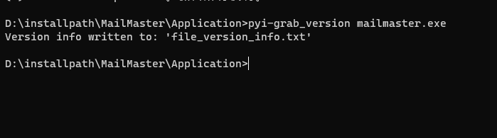
从 PyInstaller-pyi-grab_version 生成的可执行文件中提取版本信息 1. 要使用pyi-grab_version,您需要先安装PyInstaller。您可以使用pip来安装它。在Windows 终端(cmd)中输入以下命令:pip install pyinstaller2. 我们需要在 Windows终端 中进入您要获取版本的程序目录下,执行以下命令操作。pyi-grab_version yourprogramname.exe3.当命令执行完成后,会在目录下生成一个file_version_info.txt名称的文件。# UTF-8 # # For more details about fixed file info 'ffi' see: # http://msdn.microsoft.com/en-us/library/ms646997.aspx VSVersionInfo( ffi=FixedFileInfo( # filevers and prodvers should be always a tuple with four items: (1, 2, 3, 4) # Set not needed items to zero 0. filevers=(1, 0, 0, 0), prodvers=(1, 0, 0, 0), # Contains a bitmask that specifies the valid bits 'flags'r mask=0x16, # Contains a bitmask that specifies the Boolean attributes of the file. flags=0x0, # The operating system for which this file was designed. # 0x4 - NT and there is no need to change it. OS=0x40004, # The general type of file. # 0x1 - the file is an application. fileType=0x1, # The function of the file. # 0x0 - the function is not defined for this fileType subtype=0x0, # Creation date and time stamp. date=(0, 0) ), kids=[ StringFileInfo( [ StringTable( '080404b0', [StringStruct('CompanyName', 'Smilinghan'), StringStruct('FileDescription', 'Smilinghan-PC'), StringStruct('FileVersion', '1.0.0.0'), StringStruct('InternalName', 'Smilinghan-PC.exe'), StringStruct('LegalCopyright', 'Copyright (C) 2023-2023 by Smilinghan (nihaotang.com)'), StringStruct('OriginalFilename', 'Smilinghan-PC'), StringStruct('ProductName', 'Smilinghan-PC'), StringStruct('ProductVersion', '1.0.0.0')]) ]), VarFileInfo([VarStruct('Translation', [2050, 1000])]) ] )
-
静态路由与BFD联动 1. 配置思路:网络的需求是R2能够访问10.9.9.0/24,而且在网络正常时,R2将到达10.9.9.0/24的数据包转发给Rl,而且当Rl发生故障时,或者Rl与R2之间的某段链路发生故障时,R2自动将数据包的转发路径进行切换,将到达该网段的数据包转发给R3。并且在RI及R2上部署BFD来检测双方直连接口的P连通性。预防某个链路发生故障能感知到(静态路由无法感知到网络拓扑的变化并作出动态响应)。BFD ( BidirectionalForwarding Detection,双向转发检测)就是这类技术之一。实际上,BFD是一种实现网络可靠性的机制,它可被用于快速检测网络中的链路状况、IP可达性等。BFD可以与多种协议或机制进行联动,以确保它们更加可靠地工作,例如静态路由、OSPF、IS-IS、BGP、 VRRP、PIM 及MPLS LSP等。需注意的是,在R1的 BFD会话中,discriminator local 需与R2的 discriminatorremote 相同,而它的discriminator remote需与R2的discriminator local相同。另外,BFD会话的名称只具有本地意义,双方无需相同。R2:配置浮动静态路由ip route-static 10.9.9.0 24 10.1.12.1 ip route-static 10.9.9.0 24 10.1.23.1 preference 80激活BFD功能bfd quit创建一个BFD 会话,会话名称为R1(该名称可自定义),对端P地址为10.1.12.1bfd r2 bind peer-ip 10.1.12.1配置该BFD会话的本地标识符discriminator local 20配置该 BFD会语的远端标识符discriminator remote 10提交配置commit quit将下一跳为R1的静态路由与BFD会话 r2 进行联动ip route-static 10.9.9.0 24 10.1.12.1 track bfd-session r2配置浮动静态路由,下一跳为R3ip route-static 10.9.9.0 24 10.1.23.3 preference 80R1:bfd quit bfd r1 bind peer-ip 10.1.12.2 discriminator local 10 discriminator remote 20 commit在完成上述配置后,我们可以通过以下命令来对配置进行验证。 display bfd session all 查看路由的BFD状态.
-
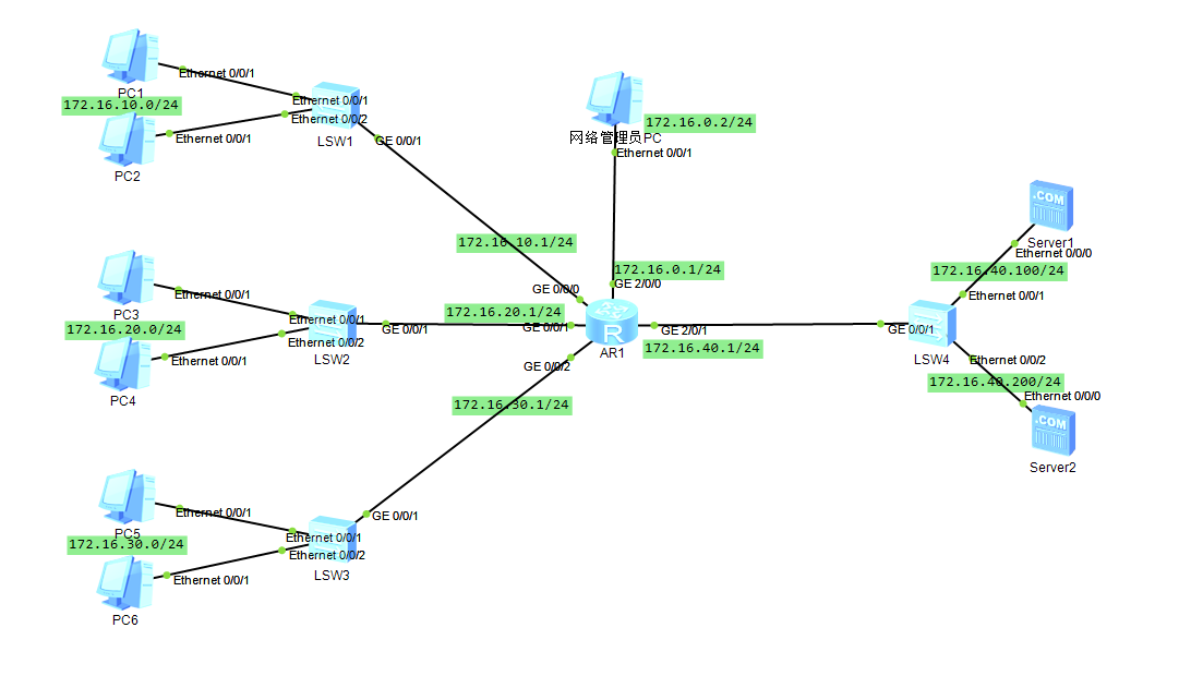
ACL 基本配置示例 1. 配置步骤:配置好基本的接口 IP 。在路由器 Router上创建ACL,注意: 必须首先进入系统视图,然后执行命令 aclacl-number。对于基本ACL,acl-number 的值必须在2000~2 999的范围内,我们这里确定为2000。另外,我们假设网管人员的PC (IP地址为 172.16.0.2)已经使用Telnet方式登录上了路由器Router。创建了基本 ACL 2000 后,我们便可以使用 rule 命令来制定相应的规则。首先,我们制定一条规则,其含义是允许(permit)源IP地址为 172.16.0.2 的IP报文。然后再制定一条规则,其含义是拒绝(deny)源IP地址为任意地址的P报文。最后,我们在VTY上应用 ACL 2000 。acl 2000 rule permit source 172.16.0.2 0 rule deny source any quit user-interface vty 0 4 acl 2000 inbound quit在完成上述配置后,我们可以通过以下命令来对配置进行验证。display acl 2000 来查看ACL 2000的配置。{dotted startColor="#e28d8d" endColor="#a9c7e5"/}1. ACL 命令:ACL分为基本ACL和高级ACL等类型。基本ACL只能基于P报文的源P地址、报文分片标记和时间段信息来定义规则。基本ACL规则的命令具有如下的结构。rule [rule-id] {deny / permit} [source {source-address source-wildcard | any}lfragment | logging | time-range time-name]2. 命令中各个组成项的解释如下:命令说明rule表示这是一条规则。rule-id表示这条规则的编号。deny / permit这是一个二选一选项,表示与这条规则相关联的处理动作。deny表示“拒绝”:permit表示“允许”。source表示源IP地址信息。source-address表示具体的源IP地址。source-wildcard表示与 source-address相对应的通配符。source-wildcard和source-address的结合使用,可以确定出一个IP地址的集合。极端情况下,该集合中可以只包含一个IP地址。通配符source-wildcard的使用方法,是与 8.3.11小节中wildcard-mask 的使用方法完全一样的,所以这里不再赘述。any表示源P地址可以是任何地址。fragment表示该规则只对非首片分片报文有效。logging表示需要将匹配上该规则的P报文进行日志记录。time-range time-name表示该规则的生效时间段为time-name,具体的使用方法这里不做描述。
-
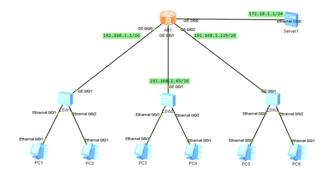
DHCP 中继代理配置示例 1. 配置步骤要在R1上配置 DHCP中继服务,必须首先进入系统视图,然后执行命令dhepenable,使能DHCP功能。接下来我们在R1的各个接口下使能 DHCP中继功能,使用的命令是 dhcp selectrelay。命令 dhcp relay server-ip 172.10.1.1用来配置DHCP Server的IP地址。R1:dhcp enable interface GigabitEthernet 0/0/0 ip address 192.168.1.1 26 dhcp select relay dhcp relay server-ip 172.10.1.1 quit interface GigabitEthernet 0/0/1 ip address 192.168.1.65 26 dhcp select relay dhcp relay server-ip 172.10.1.1 quit interface GigabitEthernet 0/0/2 ip address 192.168.1.129 26 dhcp select relay dhcp relay server-ip 172.10.1.1 quit在完成上述配置后,我们可以通过以下命令来对配置进行验证。 display this 查看相关的DHCP中继配置,注意:需要进入接口才使用该命令。
-
DHCP Server配置示例 1. 配置步骤:(1) 要在R1上使能 DHCP功能,必须先进入系统视图,然后执行命令 dhcp enable。(2) 我们在R1上创建3个不同的全局地址池,分别用于为3个不同部门的PC分配IP地址。DHCP Server 分配P地址时,可以使用基于全局地址池的服务方式,也可以使用基于接口地址池的服务方式。(3) 创建全局地址池的命令是 ip pool ip-pool-name, ip-pool-name 表示地址池名称,它可以是字母、数字、下划线等符号的组合。(4) 我们将配置 DHCP Server全局地址池中分配给网关的IP地址。命令 gateway-list ip-address 可以用来指定PC在获取到P地址后进行网络通信时应该使用的网关P地址。(5) 接下来,我们可以使用命令 lease {day day [ hour hour [ minute minmute ] ] | unlimited } 来配置IP地址的租约期。默认情况下,租约期是1天,我们这里将它配置成1个小时。(6) 我们还需要在R1的各个接口下配置基于全局地址池的服务方式,使用的命令是 dhcp select global。R1:dhcp enable ip pool department1 network 192.168.1.1 mask 26 gateway-list 192.168.1.1 lease day 0 hour 1 quit ip pool department2 network 192.168.1.64 mask 26 gateway-list 192.168.1.65 lease day 0 hour 1 quit ip pool department3 network 192.168.1.128 mask 26 gateway-list 192.168.1.129 lease day 0 hour 1 quit interface GigabitEthernet 0/0/0 ip address 192.168.1.1 26 dhcp select global quit interface GigabitEthernet 0/0/1 ip address 192.168.1.65 26 dhcp select global quit interface GigabitEthernet 0/0/2 ip address 192.168.1.129 26 dhcp select global quit 在完成上述配置后,我们可以通过以下命令来对配置进行验证。1) display ip pool namepool-name used ,查看地址池的配置情况以及已经分配的地址情况。